
by George Thiers, Timothy Sprock, and Leon McGinnis (Georgia Institute of Technology); Adam Graunke (Boeing Research and Technology); and Michael Christian (The Boeing Company)
As presented at the 2016 Winter Simulation Conference
Abstract
A multi-year research project focused on a global aerospace company’s design-to-production transition, and in particular how to answer production-related questions much earlier in a program’s design cycle than is possible today. A fundamental difficulty is that the time and expertise required to formulate appropriate analysis models prevents their routine use, especially in new program development. The project’s goal was to reduce these requirements, and by late 2014 a methodology had been developed for on-demand analysis generation to answer routine questions about production systems. A pilot project was conducted in 2015 to demonstrate efficacy, that an implementation of the methodology could in fact reduce by at least an order of magnitude the time required to answer a frequently-asked question, in a repeatable way while specification of the products, their process plans, planned facilities, and available resources were frequently changing. This paper summarizes the methodology, its pilot project implementation, and preliminary results.
Introduction
A global aerospace company seeks to improve the design of their production systems by addressing key questions earlier in the product lifecycle. Computer-Aided Design (CAD) and Engineering (CAE) tools aid product designers by providing push-button ability to evaluate mechanical, aerospace, thermal, and other types of metrics about candidate product designs. However, computational tools aiding production system designers with on-demand analysis capabilities are more limited. Therefore, the company’s vision is to enhance tool support for the design, diagnosis, and continuous improvement of production systems, beginning by giving designers push-button ability to evaluate “produceability” metrics and questions including:
- If an airplane’s design were to include novel new materials, does capability exist to make the needed parts, at a certain rate, and at a certain cost?
- If a major subassembly is partitioned into distinct sections made by different suppliers and joined at final assembly, how should the delivery schedule balance high robustness to supply disruptions and low inventory costs?
- What investment in tools, fixtures, layup molds, and other resources is needed to manufacture a certain subassembly at a certain production rate?
Whatever the list of questions, the subject of the research is how to push-button answer them, and there are several factors which make that hard. First, push-button capability requires formulating and solving a variety of operations research analysis models, including statistical, discrete-event simulation, and optimization analysis models. Solution methods and algorithms are well-studied in the literature, but not well-studied is how to formulate an analysis model given an analysis-neutral system description and a question about the system in an automated, robust, and reusable way. Second, during early design stages a product’s specification may only exist at a high level of abstraction, meaning that push-button functionality must accommodate varying amounts of detail. Third, while information about products and processes may be rigorously captured in Product Lifecycle Management (PLM) systems, information about resources and facilities is often not - production knowledge in many companies is often informal, tacit, and transient. If a company’s backbone of architecture includes CAD, Product Data Management (PDM), Manufacturing Execution Systems (MES), and Manufacturing Resource Planning (MRP), the combination of these systems still lacks information needed to answer many produceability questions, including the ones listed above. Therefore, when a designer pushes the button, they should also expect to supply additional information, which raises the questions of what exactly that information is, what language and format it should take, and what flexibility exists for its detail.
An analogy for the company’s vision is to augment personal assistants such as Apple’s Siri, Google’s Voice Search, or Microsoft’s Cortana with additional functionality needed to answer produceability questions about candidate designs. To understand how the needed functionality differs from what already exists, consider that many questions asked of personal assistants are answerable by simple database or web search. Isolated examples also exist of more advanced machinations, a popular one being computing driving directions. Questions about navigating civilian transportation networks are not commonly answered by searching through pre-recorded routes in databases, but rather by formulating a shortest-path network flow optimization analysis, solving it (perhaps using Dijkstra’s algorithm with heuristics), and doing so within seconds and invisibly to the end-user. With this analogy, the factors listed above can be summarized into two challenges: (1) A necessary generalization and expansion of personal assistants’ capabilities for analysis formulation and solution, and (2) Modeling. Answering questions about driving directions is possible because personal assistants already have detailed knowledge of civilian transportation networks. They have no knowledge, however, of an arbitrary company’s proprietary products, processes, resources, and facilities - and even if they did have access to the company’s information systems, those are not complete, nor can commonly function in the required role of an experimental design environment.
By late 2014, a methodology had been developed to address these challenges, and in particular the modeling challenge. The methodology enables push-button answering produceability questions via automatic formulation of many different analysis model types, but the pilot project focused exclusively on formulating discrete-event simulation models, consistent with Nelson’s observation that “Simulation is increasingly the only method capable of analyzing, designing, evaluating, or controlling the large-scale, complex, uncertain systems in which we are interested” (Taylor et al. 2013). A company-imposed requirement is to use commercial off-the-shelf (COTS) tools for automatically-formulated simulation models including Simio and Tecnomatix Plant Simulation.
1.1 Prior Work: Model Generation and Modeling
Many engineering analysts have tried adding automation to their workflow, following the paradigm of separating system description from system analysis, authoring system descriptions in a presumably-easier way, and then automatically transforming them into the semantics and syntax of a particular analysis language as-needed. Yuan et al. (1993) describes a generator for SIMAN-language simulation models of “discrete operational systems” which are modeled with an “operations network” and “operation equations”. Son and Wysk (2001) describe automatically building simulation models in the Arena language to answer manufacturing shop floor control questions, using a network abstraction called a “message-based part state graph” to capture potential routings through a shop’s resources. Fournier (2011) describe automatically building simulation models in various languages (QUEST, Arena, ProModel, FlexSim) using the Core Manufacturing Simulation Data (CMSD) standard, and Bergmann et al. (2012) maps CMSD to the SLX simulation language. Dong and Chen (2001) generate object-oriented Petri Nets from Computer Integrated Manufacturing Open System Architecture (CIMOSA) behavior rules, and Deavours et al. (2002) generate Stochastic Activity Networks (SAN) from modeling formalisms compatible with the Mobius framework. Simulation analysis model generators inputting SysML-language system models are Batarseh et al. (2015) and Kapos et al. (2014), the latter generating executable Discrete Event System Specification (DEVS) models.
Observe the variety of system description languages in the citations above. In addition to “discrete operational systems”, “message-based part state graphs”, CMSD, and more, there are many additional candidate languages, ranging from research ideas to adopted standards. An OASIS standard for the exchange of production planning and scheduling data is (OASIS 2011). The output of the ISO TC 184/SC4 committee includes the ISO 10303 standard for machine-readable capture and sharing of product data (Pratt 2001). AutomationML is a standard-of-standards for exchanging data between engineering tools in a production facility (Drath et al. 2008). These efforts standardize data schemas, and there are also efforts to standardize semantics and ontologies. An OMG standard formalizing business process semantics is Business Process Model and Notation (BPMN) (OMG 2011). A Supply Chain Council standard formalizing supply chain management semantics is the Supply Chain Operations Reference (SCOR) (SCC 2012). Proposals for formalizing manufacturing semantics include Manufacturing Semantics Ontology (MASON) (Lemaignan et al. 2006) and also Molina and Bell (1999), Cutting-Decelle et al. (2007), and Guerra-Zubiaga and Young (2008).
Tanenbaum (1981) observes “The nice thing about standards is that you have so many to choose from.” In the first years of the research project, the authors sought a single and “perfect” system description language for production systems (Thiers and McGinnis 2013), aggregating from various cited contributions and filling in gaps. However, nothing was ever developed which the authors could plausibly argue the whole world should use, for reasons including a fundamental tension between concrete and abstract (the former needed for user accessibility, the latter needed for robustness and reusability), and also that a language is inexorably shaped by its authors’ use cases at a moment in time. Inevitably, both the use cases and time change, the language must evolve, transformation programs which are tightly coupled to the language break, and the author must maintain code they have long forgotten, if the original author can be found at all. Progress only resumed when it was finally accepted that a single and “perfect” system description language for production systems may never exist, and a way was devised to accommodate a plethora of similar-but-different system description languages.
1.2 The Challenge of COTS Discrete-Event Simulation Tools
In addition to a large number of language choices for system description, there are also a large number of language choices for discrete-event simulation analysis - unlike the domain of optimization analysis which has a canonical language “A Mathematical Programming Language” (AMPL) (Fourer et al. 1993), to the best of the authors’ knowledge the domain of discrete-event simulation has no such canonical language, and each language choice differs from other language choices in both semantics and syntax. If there are m choices of system description language and n choices of simulation analysis language, then m n permutations of transformations from system description to simulation analysis result, severely limiting the return on investment of writing and maintaining each one. The methodology described in this paper reduces m to 1, but still allows m system description languages by adding an intermediate transformation step which loosely couples each language to a back-end bridging abstraction language.
Among the efforts cited in section 1.1 to automatically generate simulation models, there is considerable variety in where the transformation “intelligence” is located - it may be upstream in the system description language (effectively conflating that language with the downstream analysis language), in the transformation itself (as with general-purpose model-to-model transformation languages and tools including QVT (OMG 2016) and ATL (EMF 2016), or downstream in the system analysis language (effectively conflating that language with the upstream description language, the de-facto approach of many COTS simulation tool vendors). In some cases, researchers attempt to simplify transformations by writing their own discrete-event simulation language and solver, as in Biswas and Narahari (2004), Chatfield et al. (2006), and Schonherr and Rose (2009), enabling transformation of system description to simulation analysis using straightforward one-to-one mappings. In the authors’ estimation, developing ad-hoc analysis tools when suitable COTS tools are available - even if their language is inconvenient - does not seem a sustainable path. The methodology described in this paper places most of the transformation “intelligence” in model-to-model transformations themselves, but proposes a small step forward by building simulation models to the greatest extent possible using model library blocks which are executable versions of bridging abstraction model elements.
Methodology
A methodology is a collection of related processes, methods, and tools (Estefan 2008), and the process in this paper’s methodology is shown in figure 1. Both the System Model in the top-left and the Bridging Abstraction Model in the top-center are description-only, and both are actually comprised of two different levels of modeling abstraction, which might be called the schema and the data or the metamodel and the instance model, or class definitions and object instantiations in object-oriented software terminology. The system description language discussed at length in section 1.1 is the upper schema or metamodel layer, and the distinction is important because model-to-model transformations depend only on this layer and should work given any conforming data or instance model. The Bridging Abstraction Metamodel is an abstract creation capturing the underlying commonalities shared by all discrete-event logistics systems - manufacturing systems, supply chains, warehousing & distribution systems, transportation & logistics systems, healthcare delivery systems, and more. A key observation is that most systems studied in industrial engineering have a network structure, and most operations research analysis of them is network-based analysis. The bridging abstraction metamodel has evolved since its inception into a collection of layered models, but the original and fundamental layer the authors call a token-flow network, with an excerpt shown in figure 2.
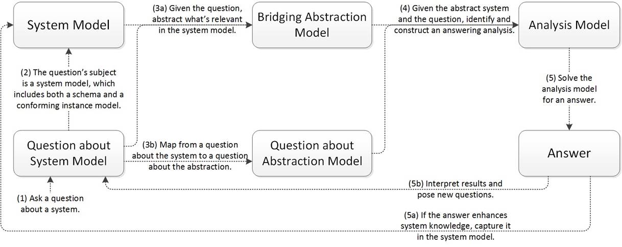
Figure 1: The methodology’s process, whose novelty is the Bridging Abstraction Model.
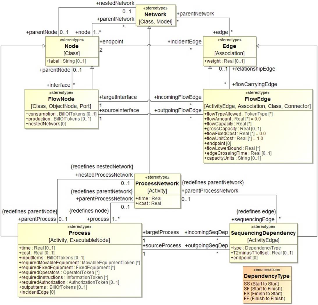
Figure 2: An excerpt from the Token-Flow Network layer of the Bridging Abstraction Metamodel.
The Bridging Abstraction Model is introduced to mediate a fundamental tension between concrete and abstract - a System Model should be as concrete as needed for accessibility, the Bridging Abstraction Model should be as abstract as possible for robustness and reusability, and efficacy depends on easily created and maintained mappings between the two. The mappings realize as declarative specifications of model-to-model transformations, and updating them in response to new or evolving system models must be as simple and fast as possible. In software terminology, the added intermediate step has the effect of mitigating tight coupling between system description languages and system analysis languages, to alleviate costs when a system description language must inevitably change with use cases and time. In figure 1, second-stage coupling between the Bridging Abstraction Model and the Analysis Model will remain tight, but first-stage coupling between the System Model and the Bridging Abstraction Model should be as loose as possible to accommodate new or evolving System Models. Importantly, due to the Bridging Abstraction Model’s stability, the task of writing and maintaining the second-stage transformations should have enough return-on-investment that might be adopted by a dedicated team, as opposed to diverse analysts.
Many new ideas are variations on old ones, and the process in figure 1 may classify as such, a transplant of best practices from software to systems engineering. The methodology’s novelty is in its methods and tools which address large research challenges exist to make this work for systems engineering:
- The Bridging Abstraction Metamodel - an explicit, analysis-neutral, and human- and machine- readable metamodel which captures the underlying commonalities shared by all discrete-event logistics systems. As the research project evolved, it quickly became clear that the bridging abstraction model would be iteratively developed for years to come. Modeling a system’s structure is usually the lowest-hanging fruit, modeling behavior (think processes) is usually more challenging, and modeling control (think business rules) is usually most challenging of all. Also, most candidate languages for authoring this metamodel (UML, SysML, Ecore, OPM, entity-relationship diagrams, and more - the language of the language) are object-oriented, and object-oriented systems modeling can be an unfamiliar way of thinking.
- Model-to-model transformations. To transform a System Model to a Bridging Abstraction Model in figure 1, the mechanism has evolved from UML stereotype application, to declarative specifications in general-purpose transformation languages including QVT and ATL, to a custom model-to-model transformation language and engine described further in section 3.
- Understanding the space of questions about production systems and the analyses capable of answering them. This challenge is intimately related to deep domain knowledge. If and when an implementation of the methodology supports a critical mass of routine produceability questions, a new challenge will arise - how to make productive use of a “question-answering genie” by asking the right questions. The authors envision that this will require capturing higher-level processes (diagnosis, continuous improvement, design, etc.) and the questions asked during each step of those processes’ execution.
An extensive discussion of the methodology’s processes, methods, and tools can be found in Thiers (2014), Sprock and McGinnis (2014), and Sprock (2016). Search for and experimentation with new methods and tools continues, for example a method of using model library blocks which are executable versions of bridging abstraction model elements, to the greatest extent possible, when building analysis models in a domain without a canonical language.
By late 2014 the methodology had matured on paper, and a pilot project was conducted in 2015 to demonstrate efficacy, that an implementation of the methodology could in fact reduce the time required to answer a frequently-asked question by at least an order of magnitude, in a repeatable way while specification of the products, their process plans, planned facilities, and available resources continually change. The steps involved were:
Step 1: Have the user choose a frequently-encountered scenario for which push-button formulation of discrete-event simulation models, to answer a variety of questions, could be very valuable. The scenario for this project involved evaluating manufacturing capacity for composite part fabrication, with the frequently- asked question “What is a minimum number of resources required to support a given production rate?” Of interest are composite layup mold and autoclave resources, which for large aerospace parts can be very expensive with long sourcing lead times.
Step 2: For the chosen scenario, create a system description language. This step requires capturing analysis-neutral semantics which users employ to talk about their business and represent it in information systems. This language iteratively evolved during the pilot project, and its state at the final iteration is captured in figure 3. Note that this is a schema-level model and not of any production system instance - it serves as a common definition for facilities, manufacturing processes, alternatives to them, desired future states for them, and more.
Does the language in figure 3 qualify as an abstract metamodel for describing arbitrary production systems? Certainly not - this is one particular user’s schema, and a minimal one for a particular use case, which may differ syntactically and even semantically from other users’ schemas. Important features include batching at the autoclave (by part volume, or by a specific bill of part types and quantities), and also

Figure 3: A system description language capturing production semantics for the scenario of evaluating manufacturing capacity for composite part fabrication. The language of the language is Ecore.
resources paired with parts through multiple process steps (composite layup molds from pre-layup until post-curing). These semantics also enable separating physical facility from functional process definitions, because a key component of the capacity question is that process plans do not execute in a vacuum, but rather execute in particular facilities which execute multiple process plans concurrently while sharing common resources. Semantics which are not included, but may be imporant in other scenarios, include jobs with deadlines, travel networks within and between facilities, routing control of jobs and resources, and more. The methodology’s innovation is that analysis generator programs are only loosely coupled to the system description language in figure 3, with the effect that those programs can keep working while the language evolves (during the pilot project, the language evolved in approximately eight iterations spaced one month apart). Said another way, the methodology relaxes the burden to make a system description language “perfect” before investing in analysis generator programs which depend on it.
Step 3: Make the question precise. This step should become superfluous once a certain level of maturity of tool support is realized, but it is imperative during early pilot projects. The task is to determine what information a question-asker expects in an answer, and how to extract or infer that information from simulation output. For the question “What is a minimum number of resources needed to support a given production rate?”, suppose that the answer returned is ‘‘x and y units of resource types A and B are minimum amounts needed to support, on average, 20 planes per month.” Is that sufficient, or are risk qualifiers also expected such as “x and y units of resource types A and B will yield only 19 planes in α% of months and only 18 planes in β% of months”? A large item for future development is returning answers with interpretations, risk qualifiers, and more. The methodology enables a decision-support tool, not a decision-making one, because decision-making should reflect a human assessment of risk, which might be the x-axis on some form of Pareto-frontier plot which is returned as a question’s answer.
Making the question precise also involved effort which was unique to the first project. Since the bulk of the work was software development, a spiral development paradigm was followed with an iteration period of about one month. The question “What is a minimum number of resources needed to support a given production rate?” became the capstone of a series of milestone questions:
- What is the (expected) (Raw Cycle Time) of a certain (Job)? A discrete-event simulation model to answer this question is the simplest-interesting one imaginable.
- What is the (expected) (Throughput) of regularly executing a certain (Job)? Answering this question requires only process simulation, without the context of a manufacturing facility, other process plans executing concurrently in that facility, resource-sharing paradigms, and more.
- What is the (expected) (Throughput) of making certain (Product)s in a certain (Facility)? Answering this question requires simulating a single manufacturing facility executing multiple process plans concurrently while sharing common resources. All that separates answering this question from the capstone question is adding an optimizer to search for minimum resource numbers.
- What is a minimum number of resources needed to support a certain throughput? Interestingly, an optimizer was never actually added; the pilot project sponsor recognized it as a simple extension and chose to better use the time adding fidelity to the system description, and in turn the automatically- generated simulation models.
Step 4: Map the front-end system model to the back-end bridging abstraction model, as much as needed to answer the question. Efficacy of the methodology depends on the loosest-possible coupling between these two models, and the loosest we can imagine is a declarative specification of a model-to-model transformation, an example of which is shown in figure 4.
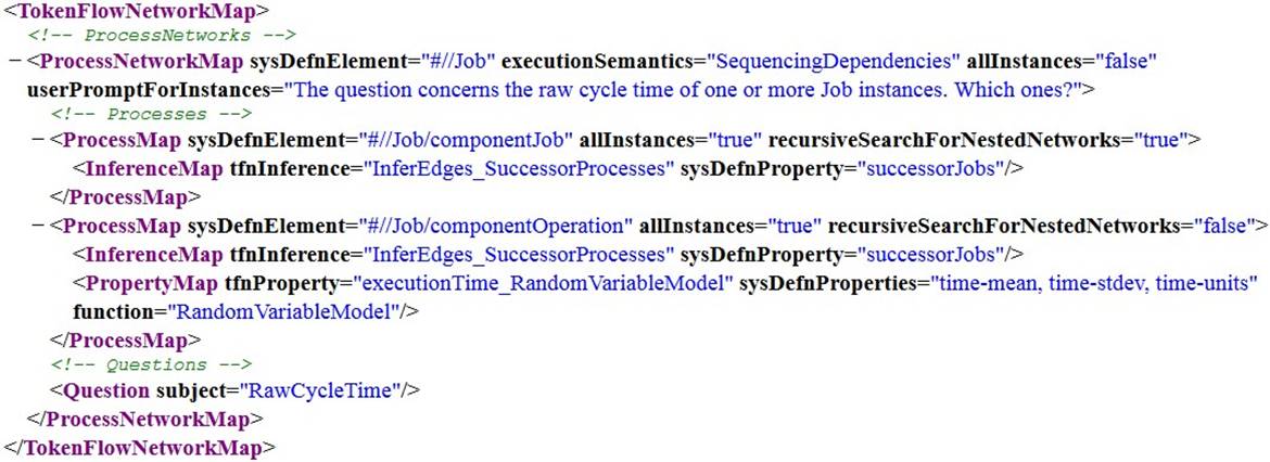
Figure 4: A model-to-model transformation from the System Model to the Bridging Abstraction Model to answer a question about raw cycle time.
The XML in figure 4 is a low-level representation which users should not be expected to interact with directly - usability improvements should make authoring and updating declarative specifications of model-to-model transformations much more user-friendly. At the project’s beginning, the authors had imagined performing these mappings via the mechanism of UML stereotype application (Batarseh et al. 2012). However, that quickly became untenable due to inflexibility - applying a UML stereotype effectively defines a one-to-one transformation rule, which constrains the system model and the bridging abstraction model to look very similar and only effectively differ in syntax. The authors next considered general-purpose and standardized model-to-model transformation languages including QVT or ATL, but transformation specifications were quite verbose, and it was quickly realized that incorporating knowledge of the transformation’s target enables dramatic simplification. This simplification incurs a loss of flexibility, but flexibility which was not needed, consistent with Cleenewerck and Kurtev (2007)’s conclusion that “The problem of translational semantics in Model-Driven Engineering is better to be approached with a domain-specific transformation language instead of with a general purpose one.” Future work includes reconciling the custom and domain-specific transformation language with a standard such as QVT.
Step 5: Create instance models and press go. To push-button answer a produceability question, the final step requires quickly describing a question’s subject - instances of products, processes, resources, and facilities. The metamodel in figure 3 is analogous to software class definitions which can engender large numbers of object instantiations, and this step requires creating those object instantiations. In the pilot project this was done in a tabular and Excel-like environment, and an excerpt is shown in figure 5.

Figure 5: An excerpt from an instance model conforming to the system description language in figure 3.
The tables and their schema in figure 5 conform to the metamodel in figure 3 - Operation maps to a table, and each attribute maps to a column. An instance model’s tables and schema are generated via object-relational mapping, and a user describes the question’s subject by filling in the tables. This is a modeling environment which could benefit from many usability improvements; one is that the tables shown to users are effectively raw relational database tables, and adding a view layer will enable simplification, organization, and hiding redundant data (for example, junction tables which follow from any attribute whose multiplicity upper bound is > 1). Another improvement is that while tables and columns are shown in figure 5 for each metamodel element in figure 3, knowledge of a user’s question enables visual filtering to only tables and columns relevant to answering that question. Another improvement is adding visualization whatever a user’s system model, as table rows are populated a bridging abstraction model is being constructed in the background, and visualization should be possible for at least process and facility views. Usability improvements to this environment are critical to realizing the maximum possible reductions of time and expertise required to answer routine produceability questions.
An example of a discrete-event simulation model and experiment which are automatically generated upon pressing go are shown in figure 6.
Conclusions and Future Work
Design-to-production transition is a complex business process, and the research described in this paper supports that process by enabling designers to appreciate production consequences of design decisions much earlier in a program’s design cycle than is possible today. A methodology was developed to enable push-button answering produceability questions, and its novelty is its degree of separating concerns - it separates system description from system analysis, and additionally separates concrete front-end system description from abstract back-end description. A pilot project implementation supports system models authored in the Ecore language, the set of questions enumerated in section 3, and push-button generation of simulation models and experiments in the Simio, SimEvents, and Tecnomatix Plant Simulation languages to answer those questions. The pilot project question concerned numbers of resources - a parametric change - and the implementation was also demonstrated to accommodate structural changes, including changes to process plans, changes to job-workstation assignments, refinement of resource types, description at levels of abstraction, and more. At the time of writing, there is no functional difference between parametric and structural changes since the implementation fully regenerates a simulation model for any change to the instance model, although this may become more sophisticated in the future for efficiency.

Figure 6: An example of an automatically-generated discrete-event simulation model and experiment, in the Simio language. The top half shows a physical facility view with shared resources and material supply, and the bottom half shows functional process views.
At the pilot project’s end, the proof-of-concept software implementation was deployed to the pilot customer. The customer estimates that for routine questions about production systems, a tool implementation of the methodology can yield a dramatic reduction in the time, cost, and expertise requirements to use simulation and other analysis types to answer those questions, at least an order-of-magnitude reduction. Those reductions can be saved, or they can be spent to evaluate more production scenarios and their impacts, consider more improvement ideas and alternatives, and explore more of a production system’s design space. However, the customer also notes that several improvements are needed to reach an advanced Technical Readiness Level (TRL) and produce a tool that analysts would welcome in their day-to-day work. The tool is a modeling and model-transformation environment, and language and user-interface improvements are needed for creating system description schemas, conforming system instance models, transformations to bridging abstraction models, and automated analysis formulation processes. These improvements will help delineate those types of questions about production systems which are in fact” routine”, and this could be a surprisingly generous set.
It is hoped that this research might grow the market for Operations Research analyses. Statistical, discrete-event simulation, and optimization analysis can answer critically-important questions, but the time, cost, and expertise requirements for their usage in the status quo can be prohibitive for all but the largest companies. There are many avenues for future work, with the most pressing in the authors’ opinion being evolving system descriptions from mostly structure to more mature models including behavior and control, and understanding higher-level processes including design, diagnosis, and continuous improvement. A deep understanding of industrial engineering systems, plus an ability to cost-effectively employ operations research analysis as-needed, are prerequisites to making the design of production systems as sophisticated as the design of products themselves.
Acknowledgements
The research reported here has been supported by Georgia Tech through the Gwaltney Chair of Manufacturing Systems, by a grant from Rockwell-Collins, and research projects funded by United Technologies Research Center and the Boeing-Georgia Tech Strategic University Partnership.