
Search the Community
Showing results for 'external nodes'.
-
 Hi, there is a simple approach you can use. Use Connectors between the queue server and the desks. At Buffer Logic of the Desks, change the Input Buffer Capacity to 0. Create a List with the Input nodes of the seven Desks. On the Output of the queue server change Entity Destination Type to Select From List and the goal to Smallest Value. Keep the default expression. It should work fine.
 -
Hi All I would like help to build a custom (subclassed) node that, OnInitialized, would populate a lists of inbound and outbound path in each node. Ideally, it would also determine and store each path's length or travel time, and whether the path is available or not (this would probably require a subclassed path as well). I want this done dynamically (automatically) because I will likely have hundreds of nodes in my model and populating (and re-populating) these lists would be very time consuming and not very conducive to an efficient design process where paths and nodes would be added/subtracted throughout the design process. First, I guess, actually...is dynamic list population possible? Any thoughts? Thanks
-
A basic photo eye object that can be used with conveyor belts. Photo eye is based on a transfer node object. It collects statistics on time in blocked state, cleared state and throughput. Transfer nodes on entered and on exited add on processes can be used as on blocking and on clearing add on processes. Photo eye has properties to define the delays for on blocked and on cleared. Photo eye will wait to complete on blocked delay to execute on blocked add on process. Similarly, photo eye will wait to complete on cleared delay to execute on cleared add on process. PE_Library.spfx
-
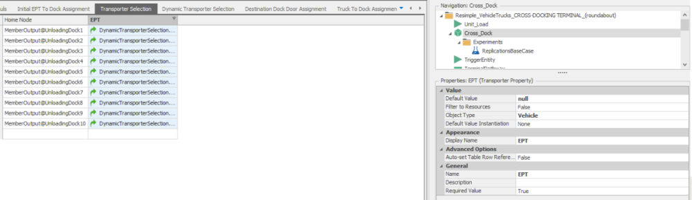
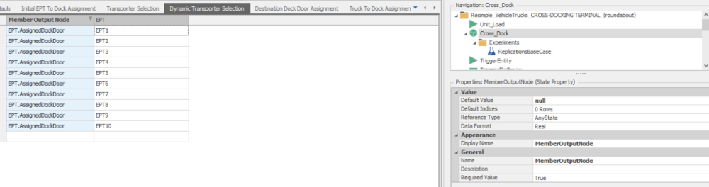
Hi all, I am building a simulation of a system with multiple separators which MemberOutput nodes two different routing policies can occur: 1. Standard Policy In the 'Standard Policy', each separator has its dedicated transporter assigned to it and entities arriving at the MemberOutputNode can only select the defined transporter. To this end, a DataTable has been constructed. 2. Power Hour policy In the 'Power Hour Policy', operations are shifted into a higher gear. We select a maximum number of three nearest transporters whose ride request is 0 and include them in the DataTable which specifies the Transporter Selection. Entities arriving at the MemberOutputNode can now request rides from any transporter in the DataTable. I tried to reference to a DataTable called 'TransporterSelection.EPT' in the Transport Logic of each MemberOutput Node. Each value in the EPT column is cross-referencing to a DataTable in which I try to assign the MemberInput Nodes as a Node Reference State Variable of the Transporter (EPT). Is there any way to dynamically assign more (or less for that matter) Transporters to a TransferNode? Hope that anyone knows how to do this! Cheers, Toon
-
Hello!
In reference to your question "How to use Simio as an external simulation routine (respectively, how to control Simio from other software e.g., R)?", did you figure out an answer that suited your needs?I saw that your question post in SI General Discussions received a post from lstretton. What was the follow-up on that? I am unsure of where to go to get further information on the steps for that. I'm new on the forum.
My problem seems to run in line with yours. I have data that populates an excel csv file and I want to import that into Simio for my simulation. Eventually I would like to automate the runs of a bunch of difference replications, potentially with R or Python or something like that.
Thanks, ftiller
-
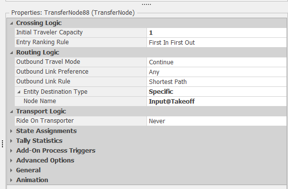
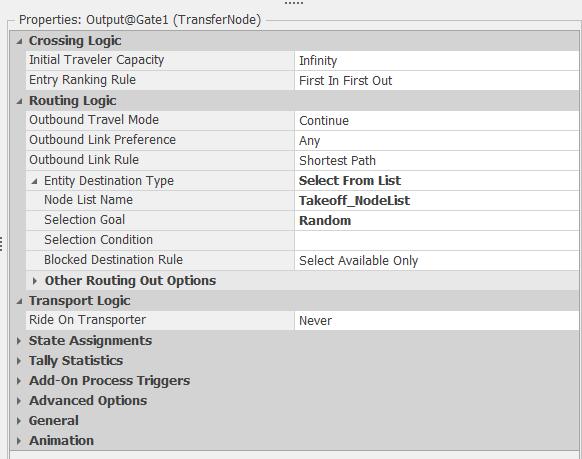
Hello River, I downloaded your files. The Gate512 was missing. I removed the information in the "30 Departure.xlxs" file that I can run the model ;-). Generally I understood how it works. Answer to your first question: I think you mean these two ways, right? From the left and from the right. In this case I saw that you used the "Routing Logic" in like all Transfernodes. The Outbound Link Rule is "Shortest Path" and you set the "Node Name" to "Input@Takeoff" Simio is using everytime the shortest link path now. Like in the screenshot below: In my opinion it would be better to set the destination once after the Entity got created in the Source for example :-). There are different ways to do that. In your model I removed all Routing Logic in the Transfernodes and used the Routing Logic only in the Output-TransferNodes of the Sources. In Simio you need only to use one time a SetNode-Step or a Routing-Logic to set the destination of an Entitiy and Simio will follow the paths or travel in the FreeSpace. You can use for example a NodeList with 2 different destinations and this Routing-Logic: With the "Selection Goal" Random Simio will randomly choose the destination from the NodeList. I uploaded you your model with the changes as an example: Problem on the taxiway version 17A.zip What did I changed? 1) I removed the Routing Logic in all TransferNodes. 2) I added new Routing Logic to the TransferNodes of the Output-Node of the Sources. 3) I added a NodeList with 2 new Nodes. 4) In the two new Nodes I used a Nodes-Entered-Process and a Transfer-Step to transfer the Entity to the Input of the Sink. Answer to your second question: You can change the destination of an Entity any time. In the Path (Link) you have a function called "NumberTravelors" for example to get the number of travelors currently on this path. So you can use a Expression like "Path123.NumberTravelors < 2". This can be used to decide if a way is full allready that the other way get selected. Or you can use a Integer-State and count up and down. I would use a Node-Entered-Process in the last possible node with a Decide-Step and two SetNode-Step in this case :-). I hope my answer will help you. When you have any other question, you are welcome! Best regards Pascal

-
Hi I want my simulation to start with some entities at the output node of a server. Is that possible? Thanks in advance Janus
-
Hi I need reference to some sort of property that can help me store entities in my transfer node(shelf). I have used the Park property but then I am not sure on how I can release it when the transporter is told to arrive at the transfer node(shelf) to pick up certain of those parked entities. Any help is appreciated. Thank you
-
Hi - I am trying to relocate nodes during run time using Relocate Object step. It works if my nodes are not connected by any links, otherwise it does not. I want my entities to follow a Network Path in Travel step, therefore, it is crucial that my nodes are connected. Any suggestion how I could achieve this? My aim is to avoid collisions when entities travel from one node to other in free space, only way I know to achieve this is through Travel step. Thanks, Zaki
-
 Hello everyone, This question has probably been answered before but i could not find any post making mention. I would like to know if it is possible to edit the position (x, y, z) of a given object via some kind of procedure or using some state to govern these values. Specifically, we would like to assign specific coordinates to nodes in a graph (so we know for example all links are scaled correctly with their size) and we would like to get the positions of the nodes from an external data source (Excel, .txt files). We would only touch these values at the beginning of the simulation (as initialization). thanks
 -
Hello, i have a project in which i must send an entity to a node, i was reading that this is possible using seize or planning a visit using the entity as resource from the destiny but i need that the entity just go to the destination i want, is this possible? any idea would be of great help Pd: the entity is based on transporter class
-
 Greetings, Trying to set up 2 separate networks (AGV and Tractor networks). I can create the Network Element in Definitions, but I cannot figure out how to assign the paths and nodes to the new networks. I tried the SetNetwork process step, but I get a runtime error: "The object or element reference 'Path 5' returned by property 'SetNetwork.EntityObject' is not of the expected type 'Entity'." How do you set a path's new Network name? Link to the model, with the runtime error (error comes from the OnRunInitialized process): https://www.dropbox.com/s/ehn33oxxed5ir43/2-Netowrks.spfx?dl=0 thanks for any help, Kurt
 -
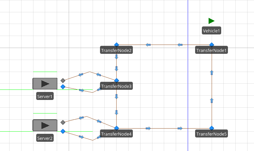
I am running some experiments on my model. I have a couple of transporters delivering fuel to three server nodes. I am trying to have the model maintain adequate fuel levels at the servers despite disruptions. Currently I have 4 responses (1 for each server and 1 that sums their fuel levels) and the responses are based on the expressions: Input@LineCompany1.AssociatedStationLoad Input@LineCompany2.AssociatedStationLoad Input@LineCompany3.AssociatedStationLoad and FuelTotal: Input@LineCompany1.AssociatedStationLoad + Input@LineCompany2.AssociatedStationLoad + Input@LineCompany3.AssociatedStationLoad I get responses as such: with the ACoFuel, BCoFuel, and CCoFuel ranging between 0 and 2 and FuelTotal ranging from 0 to 3. The capacities of these server nodes are 0 to 12 and everything is handled in integers. I am confused on how these responses are being calculated and any light that could be shed on this would be greatly appreciated.
-
 Hello, this question is related to my question here http://www.simio.com/forums/viewtopic.php?f=6&t=2352, in so far that I want to entites to go somewhere and it's a rather complex problem since I don't know which node to send the entities to before runtime. So, is it possible that I delete nodes from a nodelist during runtime? Lets say I have 4 nodes in my list and a process is triggered that deletes a node from thatlist, or a copy of that list? Thanks.
 -
 I am trying to make a routing decision based on the Candidate node's routerequestqueue's summation of the entities user-defined property. If there are different types of entities with ex. different priority levels. I would like the routing process to choose the transfernode which has the smallest total sum of it's entities priority level. the transfernode that needs to be chosen also has a routing group attached to its entity destination type rule where its final machine has 0 buffer and due to a blocked destination rule, there will be a queue build up at the transfernode that needs to be chosen. I have thought about using a state variable for each node and using add-on process each time a unit enters and leaves a node but because the main model has many multiple nodes the node's entity priority sum has to be able to be accessed through the candidate.transfernode._________________. For example during the routing step in the process section, I have candidate.transfernode.destinationroutinggroupname.routerequestqueue which gives me the node's number of units waiting, but i need to be able to access the candidate nodes summed queued property. Is there either a way to directly access this information, have looked at the expressions and having a hard time finding something. failed attempt: candidate.transfernode.destinationroutinggroupname.routerequestqueue.population.defaultentity.priority.summation or is there a way to use the add-on process where i am adding/subtracting the priority levels, but somehow attach it to the candidate.transfernode's property Hopefully this makes sense. If you look at the file, please ignore the upper half and focus on the transfer nodes maintransfer, transfernode1 and transfernode1_1. maintransfer has an entered add-onprocess which is the subject of this question. the route process and it's selection expression is what I'm trying to adjust but find a way to express the candidate transfernodes of transfernode1 and transfernode1_1 (which are part of the XferRouting group). I'd like to choose and compare the total summed priority level of each node's queue. Simple_Routing.spfx
 -
I have 2 transports delivering entities to 3 servers. What should be happening is that Transport 1 loads entities to capacity (12) then moves to Server 1 and delivers all of the entities (12). Transport 2 should load 12 entities and deliver all 12 to Server 2. Transport 1 returns to Home Node and loads 12 more entities for delivery to Server 3... and so on. However, what is happening is that both Transports are loading 12 entities then moving to Server 1 and delivering 4 entities each, then on to Server 2 and repeat and so on. I have removed and added servers to confirm that for some reason the Transports are delivering 1/#ofServers of their total capacity, conducting all of their deliveries and then returning to home once empty. I have limited the timepath to each Server to only allow 1 Transport at a time, but then Transport 2 just waits at the Home Node until Transport 1 is on its way to Server 2. Then it moves to Server 1 and just ends up one node behind Transport 1 at all times. The dispatch logic: (Server1.InputBuffer.Contents.NumberWaiting <= 12)||(Server2.InputBuffer.Contents.NumberWaiting <= 12)||(Server3.InputBuffer.Contents.NumberWaiting <= 12); set at Smallest Value for Selection Goal; Selects from a List of all Server Nodes.
-
 About the job Position: Industrial Simulation Services, Simulation Developer Location: Kitchener, Ontario Experience: 3-5 Years of relevant work experience Division: OTTO Motors Area of Study: Industrial/ Mechanical/ Mechatronics/ Systems Engineering NOTE: Must be able to travel to the U.S at time of application. About Clearpath Robotics Inc. Clearpath Robotics Inc. develops the future of robotics technology through development and sale of industry-leading self-driving technology, products, and services to over 500 of the world’s most innovative brands. Proprietary hardware, software, and services are delivered through the company’s research and industrial divisions: Clearpath Robotics and OTTO™ Motors. Clearpath Robotics Inc. is an award-winning company with recent awards including Robotics Business Review Top 50 Robotics Company, Edison Award for Innovation, Business Insider Top 40 under 40, and Canada’s Top 100 Employers. About Clearpath Robotics Research Solutions Clearpath Robotics’ research solutions group is a global leader in unmanned vehicle robotics for research and development, and provides hardware, software, and services to enable self-driving vehicle development, deployment, and operation. Clearpath Robotics works with over 500 of the world’s most innovative brands in over 40 countries, serving markets that span mining, military, agriculture, aerospace, and academia. Visit Clearpath Robotics atwww.clearpathrobotics.com. About OTTO™ Motors OTTO™ Motors is making material handling in industrial settings safer, easier, and more efficient through development of hardware and software that automates movement of goods in busy factories and warehouses. The company’s industry-leading self driving technology provides automated and on-demand material handling in the most demanding industrial environments, spanning automotive, medical device, aerospace, logistics, and more. Customers trusting their mission-critical material handling needs to OTTO Motors include Fortune 100 brands GE, Toyota, and Caterpillar. For more information visitwww.ottomotors.com. About the Job Having 10’s of robots run around our offices is great, but having hundreds of robots running around inside our computers is even better. Rich simulation environments offer a wide range of benefits to many aspects of our business: fast research, development and validation, sharp marketing tools and strong customer experience / support. We're looking for a Simulation Developer to create and run simulations that will help us optimize our robot fleets and system solutions. As a part of the Industrial Simulation Services (ISS) team, you will act as a subject matter expert and lead modeling and simulation activities. The ISS team works closely with our Systems Engineering, Applications Engineering and Project Management team, to support overall solution design from initial concept all the way to full system design and deployment. You will be building material flow strategies (based on self-driving vehicles) for products already in our arsenal and ones that do not yet exist. Your goal is to develop accurate and robust simulations to evaluate design, lower risk, and enhance the elegance of our solutions to fuel our growth. Primary Responsibilities Creating discrete event simulations for real and hypothetical systems, estimating fleet sizes, identifying traffic bottlenecks, testing what-if scenarios to optimize performance of robot fleets Consulting with project leads, sales team members and customers to obtain understanding of the requirements and to collect the necessary inputs Advising on simulation based metrics to evaluate system risks and performance Analyzing results and making recommendations for facility and material flow design Presenting your simulation results to our team of engineers, our sales team, and to clients Validating models against real world data to maintain accuracy relative to product portfolio Growing and improving our simulation library and internal templates for functionality, accuracy, scalability and efficiency Drafting functional specifications, proposals and effort estimation Recommending product feature and improvement ideas to our Product and Engineering teams, that lead to greater system optimization in the real world Additional tasks may include: Interacting with our development team as necessary to assess impact of new feature or product Developing simulation models to assist Sales & Marketing in demonstrating Clearpath's products and capabilities Using your expertise to assist our engineering services group in developing the more complex system concepts About You You're excited about the role that robots will play in the future, and intrigued by the challenge of joining a young company in this high-growth market. You have skills and experience that you know can make a difference with the Clearpath team, whether we're looking for them or not. You are driven and view work as more than just a job. You are motivated by making an impact on your workplace and you thrive on challenging and rewarding problems. Most of all, you want to be on the right side during the coming robot revolution. The ideal candidate will have: Proven success using simulation solutions to evaluate feasibility of facility design or operational changes Experience with discrete event simulation tools like Simio, AutoMod, AnyLogic, FlexSim, Delmia, and understanding of its limitations Experience collaborating with cross-functional and external client teams to gather comprehensive data required for model development and/or analysis Fearless in questioning to ensure end users get the most value out of your work. You understand the importance of early goal alignment and scope definition Effectively communicate complex model functionality to the client or internal team for assurance of model results accuracy Customer-first mindset Avid self-learner Ability to work independently with minimal supervision and manage deadlines. Able to cope with sudden jarring changes in projects, priorities, and the local gravity field. Bonus Points for: Experience identifying traffic and material flow bottlenecks and mitigating risk Experience in manufacturing industry Understanding of different industry warehouses. You see block diagrams and flowcharts everywhere and speak the language. Experience with Object-Oriented programming Working knowledge of one or more of C#, Python, VB.NET Exposure to working with ROS, Gazebo Past participation in simulation challenges What’s in it for you: Flexible Hours, Health Benefits, Parental Leave, Vacation, Equity, Community Days (paid), Half-Day Birthdays, Passionate and Dedicated Teams Curious to know more about the culture at Clearpath & OTTO, check out: https://clearpathrobotics.com/blog/category/blog/culture/ Come join us if you feel like our values resonate with you, and if you are interested in being a part of making industrial workplaces safer and revolutionizing automation. At Clearpath, we are committed to building and supporting a culture of diversity, inclusion, and accessibility. We hire the best talent regardless of race, color, creed, national origin, ancestry, disability, marital status, age, veteran status, six, sixual orientation, gender identity, and expression. If you require special accommodation to complete any portion of the application or interview process, please contact 1-800-301-3863.
 -
Hi All This has probably never really come up for most of you, but is there a way of using a button to open an external file (like a PDF)? I just want the system to open a reference document from within a simulation. It's ok (actually preferable) for the file to open outside Simio; it just makes for a good contact to relevant supporting information. Thanks
-
 Senior Industrial Engineer - Simulation Req #: 67308BR York, Pennsylvania, United States Engineering & Technology Platforms & Services Posted on:03/29/2021 Job Summary Career Level Experienced Travel Percentage 10% Full-Time / Part-Time Full-Time Clearance Level - Must Currently Possess None Shift 1st Shift Relocation Available Yes ITAR: U.S Citizen or Green Card Required Yes Clearance Level - Must Be Able to Obtain None Job Description What motivates you? If the answer is a position where you can develop your skills and earn opportunities for advancement while being part of a forward looking team then this is what awaits you in a career at BAE Systems. Our employees work on the world’s most advanced combat vehicle systems. From the M109A7 Mobile Howitzer with its long range firepower to the Amphibious Combat Vehicle that transports America’s Marines from ship to shore, we are developing the technology of tomorrow while delivering the most cutting-edge equipment available today. Our flexible work environment provides every opportunity to positively impact the company without giving up your personal life and we welcome all those who understand the importance of improving production velocity, having big ideas, and craving innovation. We draw strength from our diversity and always put our customers first through an unwavering commitment to bring the warfighter home safe. Does this sound like a team you want to be a part of? If so, come build your career with BAE Systems. The Combat Vehicles line of business within the Platforms & Services (P&S) Sector of BAE Systems is looking for a self-motivated Senior Industrial Engineer to support the production scheduling of armored military vehicles. Working as a team member of a larger Industrial Engineering Group, this Engineer will be required to build and maintain simulations for varied fabrication, assembly, and testing processes. The candidate must also be comfortable with soliciting input through face to face interaction and, in general, must demonstrate that they possess strong analytical, problem-solving, and interpersonal skills that will support individual and team growth. A strong background in discrete event simulation, specifically with the use of SIMIO, is necessary. Specific responsibilities include: Day-to-Day · Complete simulation support activities such as time studies, production line balancing and production metric development · Evaluate complex Technical Data Packages (Drawings, Bills of Material) and be able to understand how a component or vehicle is assembled · Utilize a strong understanding of integration activities like implementation of standard work, material kitting, metric tracking, and process improvement to advance manufacturing methods. · Work on the manufacturing floor with other Engineering disciplines, production supervisors, and employees that directly interact with the components or vehicles being produced. Internal and External Customer Relationships · Engage in regular communications with production support, planning, logistics, quality, manufacturing supervisors, and direct labor workforce to assess operations performance. · Summarize and present findings to internal customers to gain buy-in for improvement efforts · Discuss the status of metrics and key performance indicators with appropriate decision makers Development · Work with Industrial Engineering leadership to understand the expectations of new Engineer within the organization and company · Share responsibility of self-development with immediate supervisor · Maintain a safe work environment and ensure compliance with safety objectives and policies. Required Education, Experience, & Skills - 4+ years of simulation experience within SIMIO - BS degree from an accredited university Preferred Education, Experience, & Skills Demonstrated capability with the use and application of SIMIO discrete event simulation software. About BAE Systems Platforms & Services BAE Systems, Inc. is the U.S. subsidiary of BAE Systems plc, an international defense, aerospace and security company which delivers a full range of products and services for air, land and naval forces, as well as advanced electronics, security, information technology solutions and customer support services. Improving the future and protecting lives is an ambitious mission, but it’s what we do at BAE Systems. Working here means using your passion and ingenuity where it counts – defending national security with breakthrough technology, superior products, and intelligence solutions. As you develop the latest technology and defend national security, you will continually hone your skills on a team—making a big impact on a global scale. At BAE Systems, you’ll find a rewarding career that truly makes a difference. The Platforms & Services (P&S) sector under BAE Systems, Inc does the big stuff: the armored combat vehicles, naval guns, missile launchers, and naval ship repair…just to name a few. Our employees take pride in the work they do and why they do it. They are on the front lines every day, building our products to protect the lives of those who serve. We may be biased, but we think P&S does some of the coolest work around, and we think you will too. At BAE Systems, we celebrate the array of skills, experiences, and perspectives our employees bring to the table. For us, differences are a source of strength. We’re laser-focused on high performance, and we work hard every day to nurture an inclusive culture where all employees can innovate and thrive. Here, you will not only build your career, but you will also enjoy work-life balance, uncover new experiences, and collaborate with passionate colleagues. https://jobs.baesystems.com/global/en/job/67308BR/Senior-Industrial-Engineer-Simulation Thanks, Jenny Ridings, PHR Principal Talent Acquisition Specialist BAE Systems My pronouns are she / her M: +1 904 570 2489 | E: jenny.ridings@baesystems.com https://jobs.baesystems.com Connect with BAE Systems: Join our talent community!
 -
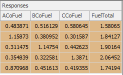
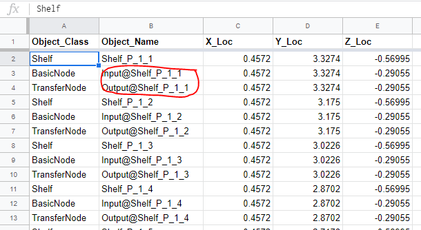
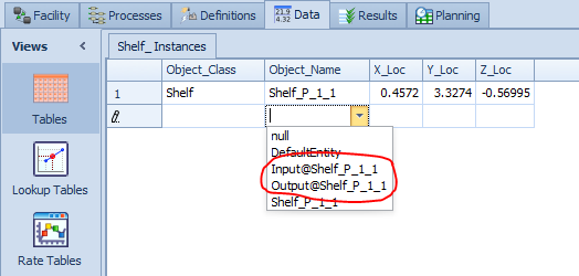
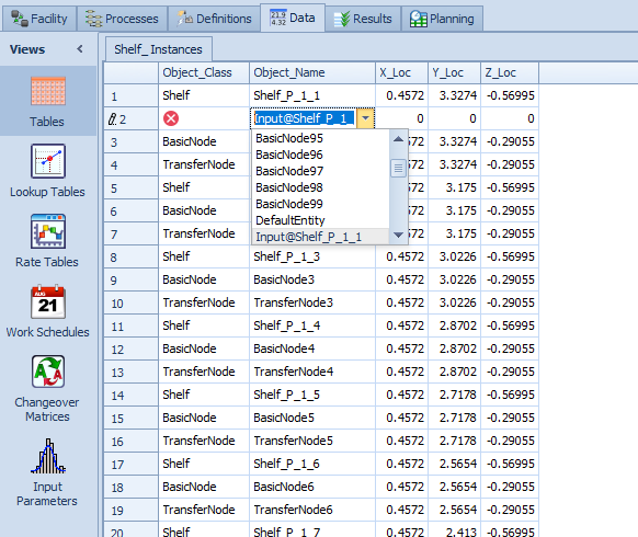
 To model shelves, I am trying to create a series of custom "Shelf" objects (subclass of servers) located in a grid pattern. I used a spreadsheet to automatically calculate the coordinate locations and generate a name (string) for each object based on its position within the grid. With just the Shelf object types in the spreadsheet, can bind the file to my object reference table no problem, import the data, and populate the facility window with my objects. That part works fine! Next, since I have an aisle running between the rows of objects, I wanted to set it up so that the objects all face "inwards", ie. the input and output nodes for the objects are facing the aisle. Originally I thought of rotating the Shelf object, but I ran into 2 issues: first, I discovered that I can't set the Shelf yaw orientation from the table, so that's not going to work. Second, I realized that even when I rotate the Shelf in the facility window, the nodes do not rotate with their parent object. I decided I would leave the Shelf in the same orientation as it is placed, but I would just re-locate the input/output nodes to the opposite edge of the Shelf objects on the far side of the aisle. For this I would need to make sure I can set locations for the input/output nodes in the same object reference table. When I added a row to the object reference table from within Simio (prior to binding to a spreadsheet), a drop down appeared, and I could select the input or output nodes for any object that already existed in the table, and then define the node's location in the cartesian coordinate columns. When creating a node this way, the node location is still relative to the object, ie. I can drag the object in the facility window and the node moves relative to the object, which is perfect. This input/output node creation and relative location definition via table is exactly what I am trying to automate, but this is where I started running into problems. In my spreadsheet I used formulas to generate names for the nodes to match the formatting of the input and output nodes in Simio (ex. "Input@..."/"Output@..."). I also added a formula to assign all input node object types to BasicNodes and all output nodes to TransferNodes and calculate the desired location coordinates for the nodes. The spreadsheet I made has the same format as the table in Simio where I tested manually creating and positioning the nodes. The issue is that when I bind the table and import the spreadsheet data to my model, the node names automatically change and are no longer formatted to reference the parent object. Because of this, these name-changed node objects are created in addition to the input and output nodes that are created for each Shelf object. However, if I remove the binding and add a new row, once again I can find the node name in the drop down list and assign the coordinates manually, and the input/output node that references the parent object will move to where I send it. My question is: how can I set the input/output node locations for the objects when creating objects from a table? There are over 500 Shelf objects in the table so I do not want to locate them manually, but the automated method is not working either. The only idea that I have is to make a new object "Shelf2" and define the external view to have the nodes on the opposite side, but that seems like a less-than-idea solution because then I would have 2 custom objects to update and maintain, that are otherwise identical. I am hoping that I don't have to do this hacky solution but I am interested to see if anyone else has dealt with this and has ideas. Thanks!
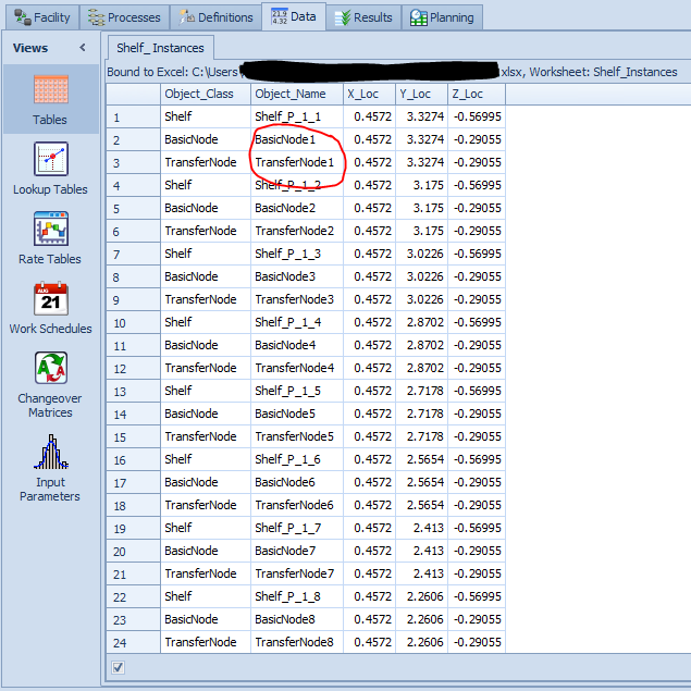
-
 Hi guys, It’s been a while that I am not able to link two nodes on ArcGIS World Street Map. The error is: “A route could not be created between ‘TransferNode1’ and ‘TransferNode2. Either a route doesn’t exist or the routing service could not be contacted’. I tried different locations, but got the same result. This is while there wasn’t any problem before and the quality of my internet connection is ok. I am wondering what the problem is! Thanks in advance for the answers, Milad
 -
In fact, even if I use just two simple nodes without any steps and other objects, it is not possible to create a street route on map, while it was possible until about a month ago. The features of my software are as follows: Version: 12.205.20430 (64bit) License Type: Academic RPS Expiration: 2021 - 06- 30 Best regards, Milad
-

Multiple Entity with multiple sequence tables
USP2010 replied to JanainaF's topic in SI General Discussions
To Whom It May Concern, I also have a very similar issue with multiple entities and multiple paths (for some entities). Could I also have the solution shared in this forum? I have tried multiple sources, transfer nodes, and sequence tables. I just seem to be running into different errors trying to achieve the same goal. Thank you, in advance, for your assistance! -
 Today, I found this topic talks about updating data in real-time when simulation is running. I thought it could be useful for me in the future so I decided to try it myself. But, when I used the Read/ExcelRead Step, I found it only "read" the external file at the first time: It seems the Read Step creates a copy of the external file at the first read and then it will use the copy for the future reads within the simulation. For example, at the start of my simulation, I used a button to call ExcelRead Step to read a excel file. Then, I manually changed some values in the excel file and I called the ExcelRead Step again. However, the second ExcelRead Step didn't read the changed values.If I want to use the changed values, I need to restart the simulation. For the Write/ExcelWrite Step, only when I stop the simulation, the external file will be updated. If I don't stop the simulation, no matter how many times I call Write/ExcelWrite Step, the external file is not changed. Are these kinds of behavior bugs? Because from the above topic, I think the Read and Write step can update the external file within the simulation. My Simio version is 12.207.20659. Thanks to everyone in advance!
-
- 1
-

-
- user defined step
- read step
- (and 1 more)
-
Hello everyone, I need some help with this please: I have 3 models in which the entity has free space movement with a specific sequence for each one. I put these 3 models (defining the external nodes) in one model and I want the entity to go in one of the 3 models with a certain probability. So I defined 3 connectors (one for each model) by weight logic and I specified the probability. Then I defined the entity Initial Travel Mode as "Network if possible" because the entity has to be able to travel in the connector, I defined a general sequence that cointains all the 3 models and then I assigned a sequence placing the SetRow Step in the Add-On Process when the entity enters one submodel. All the nodes are transfernodes with destination fixed as By Sequence. At this point I have 2 problems: - The entity does not follow the sequence that I assigned in each model because it tries to find a network, so it seems that it can not run in free space and so it does not follow the sequence table. Maybe it is because before entering a submodel it runs in the connector and not in free space from the beginning. - I defined the sequence and the logic in each model and I want that the entity exits the model when a state is equal to a specific number. In order to do this I defined a Decide Step in order to detect when the state is equal to that number and a SetNode specifying the outbound node of my submodel. When I run the model an error appears saying that the node is not in the same model where the entity is currently running. I do not understand why since the node, that is an outbound node, should be present in both models (the submodel and the entire model).